Traffic isolation and IP allocation with VLANs
When you plan for VLANs, you start with several subnets, from which you allocate individual IP addresses. When you use multiple subnets you can separate traffic between systems into VLANs.
For example, it is ideal that your management or API traffic is not on the same network as systems that serve web traffic. Traffic between VLANs travels through a router where you can implement firewalls to govern traffic flow.
You must plan your VLANs as part of your overall plan that includes traffic isolation, high availability, and IP address utilization for the various types of virtual networking resources in your deployment.
Required data center networks
Red Hat OpenStack Services on OpenShift (RHOSO) requires a standard set of physical data center networks to isolate different types of network traffic and ensure reliable service communication.
- Control plane network
- Used by the OpenStack Operator for Ansible SSH access to deploy and connect to the data plane nodes from the Red Hat OpenShift Container Platform (RHOCP) environment. This network is also used by data plane nodes for live migration of instances.
- Designate network
- Used internally by the RHOSO DNS service (designate) to manage the DNS servers. For more information, see DNS service dedicated networks in Extend.
- Designateext network
- Used to provide external access to the DNS service resolver and the DNS servers.
- External network
-
An optional network that is used when required for your environment. For example, you might create an external network for any of the following purposes:
- To provide virtual machine instances with Internet access.
- To create flat provider networks that are separate from the control plane.
- To configure VLAN provider networks on a separate bridge from the control plane.
- To provide access to virtual machine instances with floating IPs on a network other than the control plane network.
Note When an external network is used for workloads, an OVN gateway is required in some use cases. For more information, see on use cases and available options, see Configure a control plane OVN gateway with a dedicated NIC in Configure.
- Internal API network
- Used for internal communication between RHOSO components.
- Octavia network
- Used to connect Load-balancing service (octavia) controllers running in the control plane. For more information, see Octavia network in Extend.
- Storage network
- Used for block storage, RBD, NFS, FC, and iSCSI.
- Storage Management network
-
An optional network that is used by storage components. For example, Red Hat Ceph Storage uses the Storage Management network in a hyperconverged infrastructure (HCI) environment as the
cluster_networkto replicate data.Note For more information about Red Hat Ceph Storage network configuration, see "Ceph network configuration" in the Red Hat Ceph Storage Configuration Guide:
- Red Hat Ceph Storage 7 Configuration Guide
- Red Hat Ceph Storage 8 Configuration Guide
- Red Hat Ceph Storage 9 Configuring > Ceph network configuration
- Tenant (project) network
- Used for data communication between virtual machine instances within the cloud deployment.
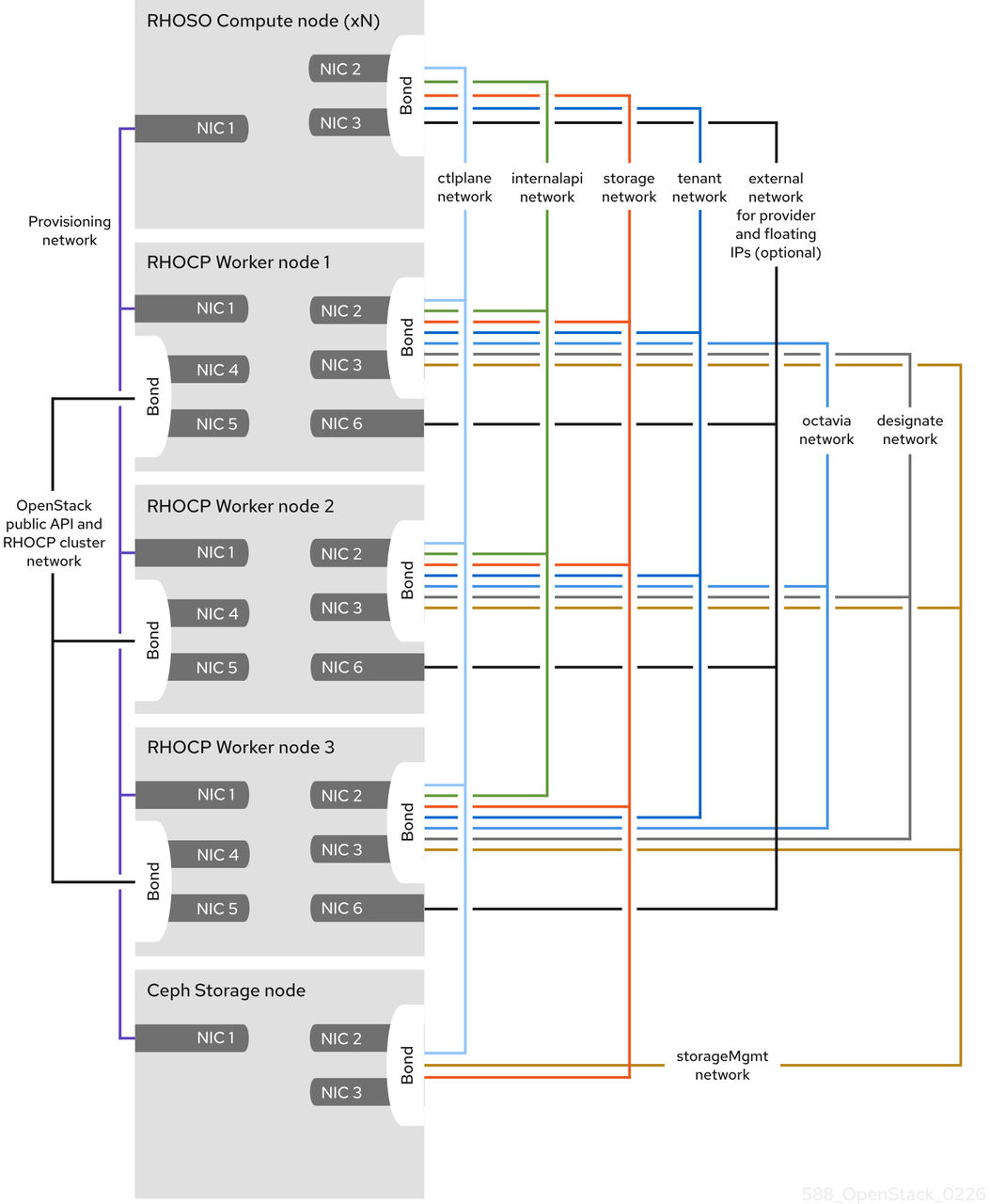
The following table details the default networks used in a RHOSO deployment.
| Network name | CIDR | NetConfig allocation range |
MetalLBIPAddressPool range |
net-attach-def IPAM range |
RHOCP workernncp range |
|---|---|---|---|---|---|
|
|
192.168.122.0/24 |
192.168.122.100 - 192.168.122.250 |
192.168.122.80 - 192.168.122.90 |
192.168.122.30 - 192.168.122.70 |
192.168.122.10 - 192.168.122.20 |
|
|
172.26.0.0/24 |
n/a |
n/a |
172.26.0.30 - 172.26.0.70 |
172.26.0.10 - 172.26.0.20 |
|
|
172.34.0.0/24 |
n/a |
172.34.0.80 - 172.34.0.120 |
172.34.0.30 - 172.34.0.70 |
172.34.0.10 - 172.34.0.20 |
|
|
10.0.0.0/24 |
10.0.0.100 - 10.0.0.250 |
n/a |
n/a |
n/a |
|
|
172.17.0.0/24 |
172.17.0.100 - 172.17.0.250 |
172.17.0.80 - 172.17.0.90 |
172.17.0.30 - 172.17.0.70 |
172.17.0.10 - 172.17.0.20 |
|
|
172.23.0.0/24 |
n/a |
n/a |
172.23.0.30 - 172.23.0.70 |
n/a |
|
|
172.18.0.0/24 |
172.18.0.100 - 172.18.0.250 |
n/a |
172.18.0.30 - 172.18.0.70 |
172.18.0.10 - 172.18.0.20 |
|
|
172.20.0.0/24 |
172.20.0.100 - 172.20.0.250 |
n/a |
172.20.0.30 - 172.20.0.70 |
172.20.0.10 - 172.20.0.20 |
|
|
172.19.0.0/24 |
172.19.0.100 - 172.19.0.250 |
n/a |
172.19.0.30 - 172.19.0.70 |
172.19.0.10 - 172.19.0.20 |
IP address allocation for nodes and VIPs
Review IP address consumption by physical nodes and virtual IP address pools.
- Physical nodes - Each physical NIC requires one IP address. It is common practice to dedicate physical NICs to specific functions. For example, allocate management and NFS traffic to distinct physical NICs, sometimes with multiple NICs connecting across to different switches for redundancy purposes.
- Virtual IPs (VIPs) for High Availability - Plan to allocate between one and three VIPs for each network that controller nodes share.
Virtual networking resources and IP allocation
Review virtual networking resources and their IP address consumption.
Virtual resources consume IP addresses in your RHOSO environment. These resources are considered local to the cloud infrastructure, and do not need to be reachable by systems in the external physical network.
The resources include:
- Project networks - Each project network requires a subnet that it can use to allocate IP addresses to instances.
- Virtual routers - Each router interface plugging into a subnet requires one IP address.
- Instances - Each instance requires an address from the project subnet that hosts the instance. If you require ingress traffic, you must allocate a floating IP address to the instance from the designated external network.
- Management traffic - Includes OpenStack Services and API traffic. All services share a small number of VIPs. API, RPC and database services communicate on the internal API VIP.
Network subnet allocation example
Review an example network plan with subnet address ranges and allocations.
- Example subnet plan
-
Subnet name Address range Number of addresses Subnet Mask Provisioning network
192.168.100.1 - 192.168.100.250
250
255.255.255.0
Internal API network
172.16.1.10 - 172.16.1.250
241
255.255.255.0
Storage
172.16.2.10 - 172.16.2.250
241
255.255.255.0
Storage Management
172.16.3.10 - 172.16.3.250
241
255.255.255.0
Tenant network (Geneve/VLAN)
172.16.4.10 - 172.16.4.250
241
255.255.255.0
External network (incl. floating IPs)
10.1.2.10 - 10.1.3.222
469
255.255.254.0
Provider network (infrastructure)
10.10.3.10 - 10.10.3.250
241
255.255.252.0
Multi-tenancy networking with subnets
Plan your subnets to provide secure, efficient multi-tenancy networking.
Subnets enable network connectivity to instances. A subnet is a pool of IP addresses. Instances are assigned to a Networking service (neutron) network. One network can have multiple subnets, and you can also add IP addresses from multiple subnets to the port.
You can create subnets only in pre-existing networks. Project networks in the Networking service can host multiple subnets. This is useful if you intend to host distinctly different systems in the same network, and prefer a measure of isolation between them.
You can decrease network latency and load by grouping systems in the same subnet that require a high volume of traffic between each other.

'%20d='M201.5%20305.5c-13.8%200-24.9-11.1-24.9-24.6%200-13.8%2011.1-24.9%2024.9-24.9%2013.6%200%2024.6%2011.1%2024.6%2024.9%200%2013.6-11.1%2024.6-24.6%2024.6zM504%20256c0%20137-111%20248-248%20248S8%20393%208%20256%20119%208%20256%208s248%20111%20248%20248zm-132.3-41.2c-9.4%200-17.7%203.9-23.8%2010-22.4-15.5-52.6-25.5-86.1-26.6l17.4-78.3%2055.4%2012.5c0%2013.6%2011.1%2024.6%2024.6%2024.6%2013.8%200%2024.9-11.3%2024.9-24.9s-11.1-24.9-24.9-24.9c-9.7%200-18%205.8-22.1%2013.8l-61.2-13.6c-3-.8-6.1%201.4-6.9%204.4l-19.1%2086.4c-33.2%201.4-63.1%2011.3-85.5%2026.8-6.1-6.4-14.7-10.2-24.1-10.2-34.9%200-46.3%2046.9-14.4%2062.8-1.1%205-1.7%2010.2-1.7%2015.5%200%2052.6%2059.2%2095.2%20132%2095.2%2073.1%200%20132.3-42.6%20132.3-95.2%200-5.3-.6-10.8-1.9-15.8%2031.3-16%2019.8-62.5-14.9-62.5zM302.8%20331c-18.2%2018.2-76.1%2017.9-93.6%200-2.2-2.2-6.1-2.2-8.3%200-2.5%202.5-2.5%206.4%200%208.6%2022.8%2022.8%2087.3%2022.8%20110.2%200%202.5-2.2%202.5-6.1%200-8.6-2.2-2.2-6.1-2.2-8.3%200zm7.7-75c-13.6%200-24.6%2011.1-24.6%2024.9%200%2013.6%2011.1%2024.6%2024.6%2024.6%2013.8%200%2024.9-11.1%2024.9-24.6%200-13.8-11-24.9-24.9-24.9z'/%3e%3c/svg%3e)